Technical Drawing Two Point Perspective
If you really want an accurate two point perspective drawing carry out the following process:
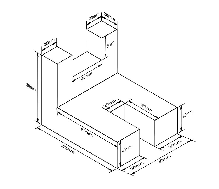
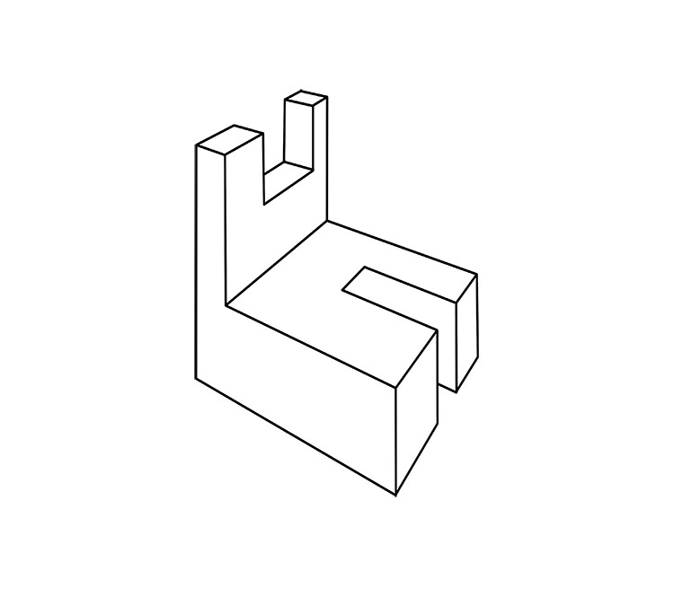
Note: We will make an accurate two point perspective drawing of the object we created in isometric drawing as below:
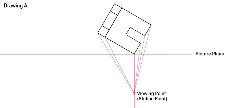
The first line to draw is a horizontal line (called a picture plane). On that horizontal line we will draw the corner of our object.
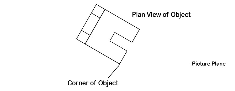
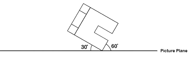
The angle to the picture plane can be anything you want but we have chosen 30 degrees.
Now we are going to choose a viewing point (called a station point). The viewing point should be vertically down from the corner of our object (vertical red line).
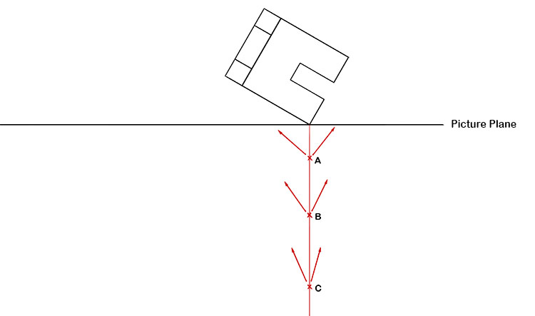
The view from view A is too wide.
The view from view C is too narrow.
View B would give us an excellent viewing point of the object.
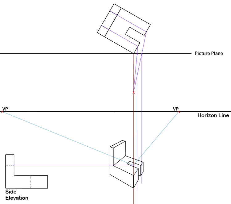
Now we have chosen viewing point B we need to draw lines connecting corners on our object to the viewing point and mark the points where these lines cross the picture plane. Unlike with one point perspective, we will only be connecting corners that are on the two sides of our plan view that are closest to the picture plane. Because of the foreshortening created by two point perspective we will need to work out the rest of the corners using a different technique which we will cover once we have the base of our object drawn.
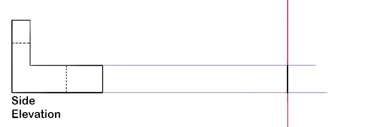
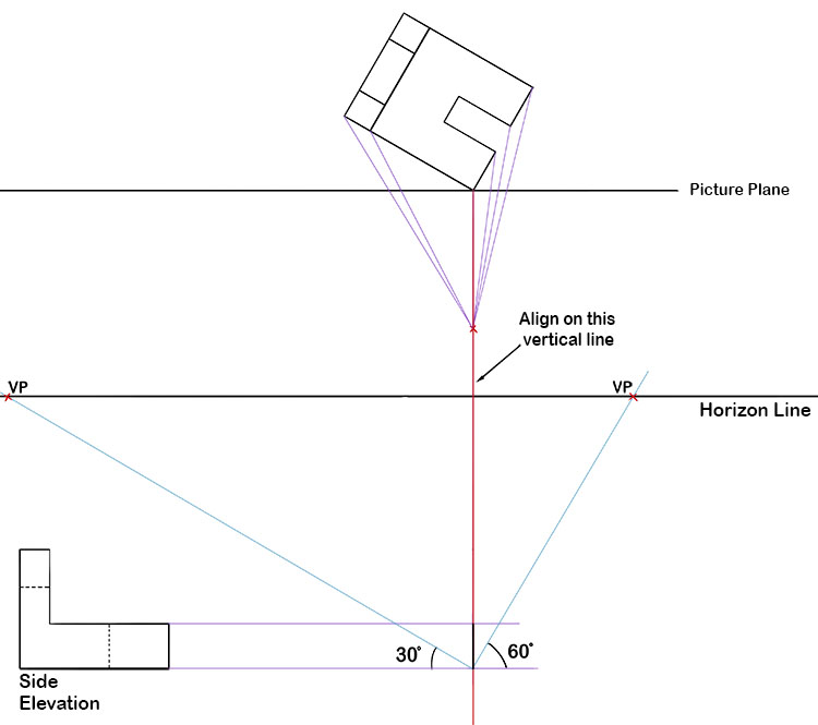
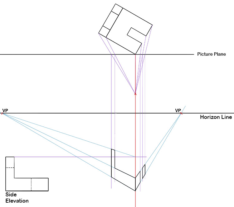
Your next step is to draw the side elevation of your object on the left hand side and project the leading edge on to a vertical line (shown in red).
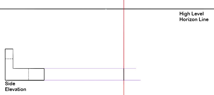
Decide whether you want a high level horizon line or low level horizon line. We have drawn a high level horizon line.
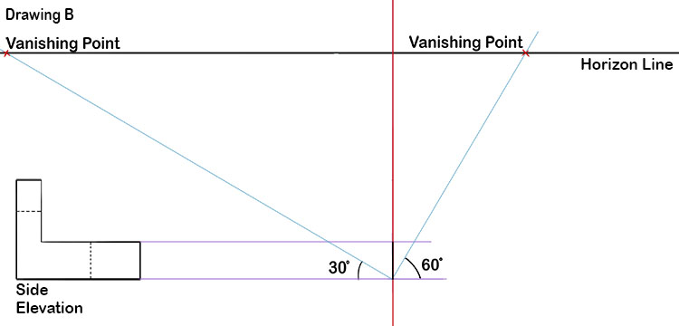
On the chosen horizon line we are going to use two vanishing points that are quite wide apart. The points could be placed arbitrarily but where they are affects the view and with practice you will learn the difference. Here we are going to follow the angle of the plan view of the object to the picture plane in the very first drawing we drew above i.e. 30 degrees and 60 degrees.
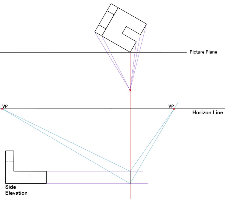
Now you need to align drawing A with drawing B along the red vertical line.
Project the top of the front vertical edge to the chosen vanishing points as well.
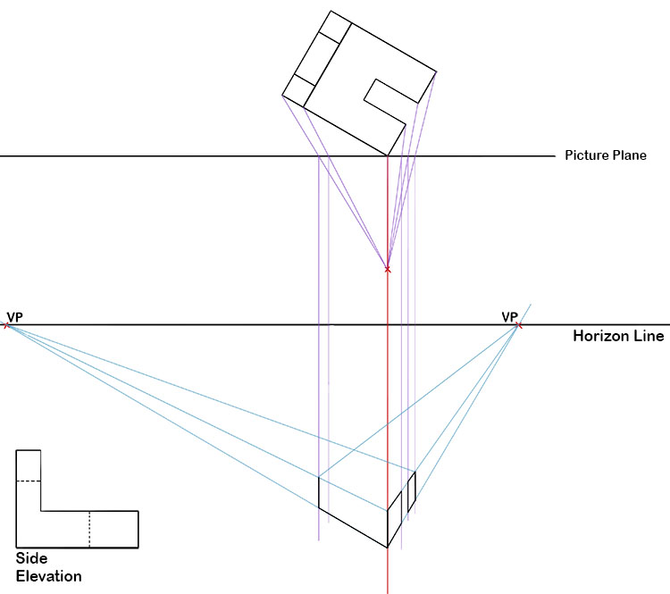
Now drop down vertically all the points where your viewing point (station point) passes the picture plane. Now we can draw in the two sides closest to the picture plane on our plan view.
To calculate the height of the raised section at the back of our object we need to draw a line from the top of the side elevation (point A) to the red vertical line. From the point where these two lines meet we can draw a line to the left hand vanishing point. You can now continue the rear edge to meet this line.
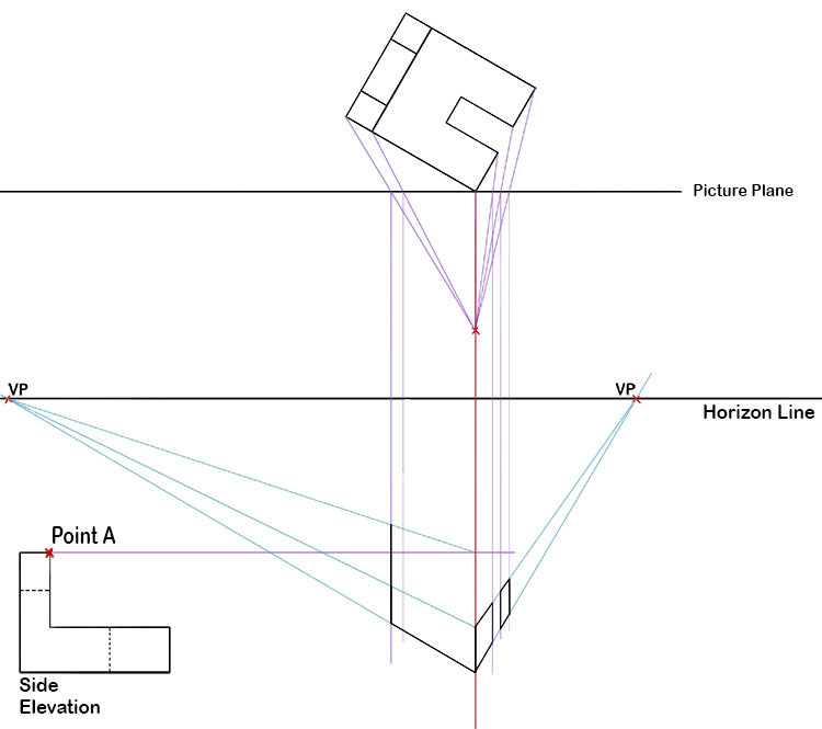
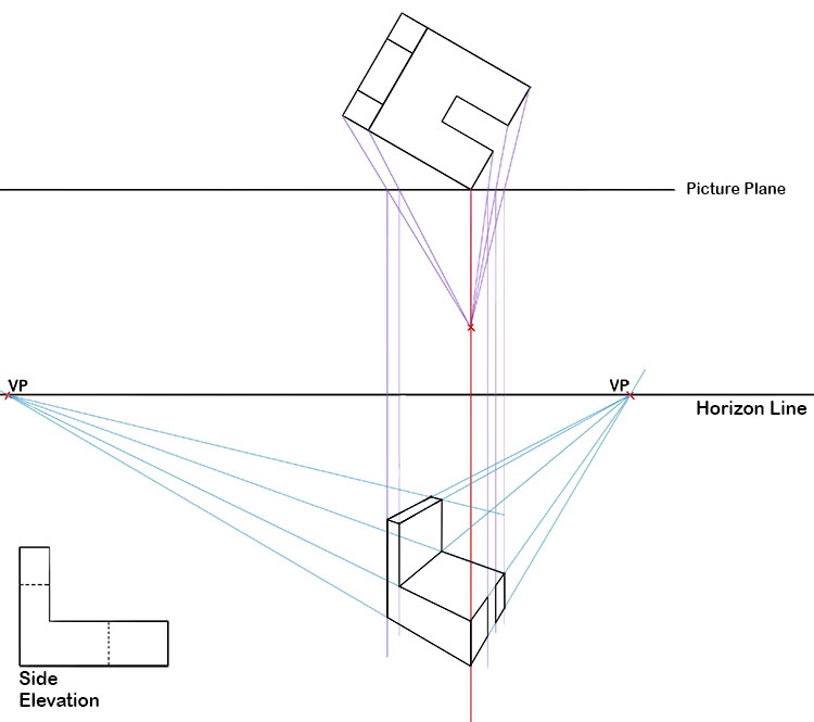
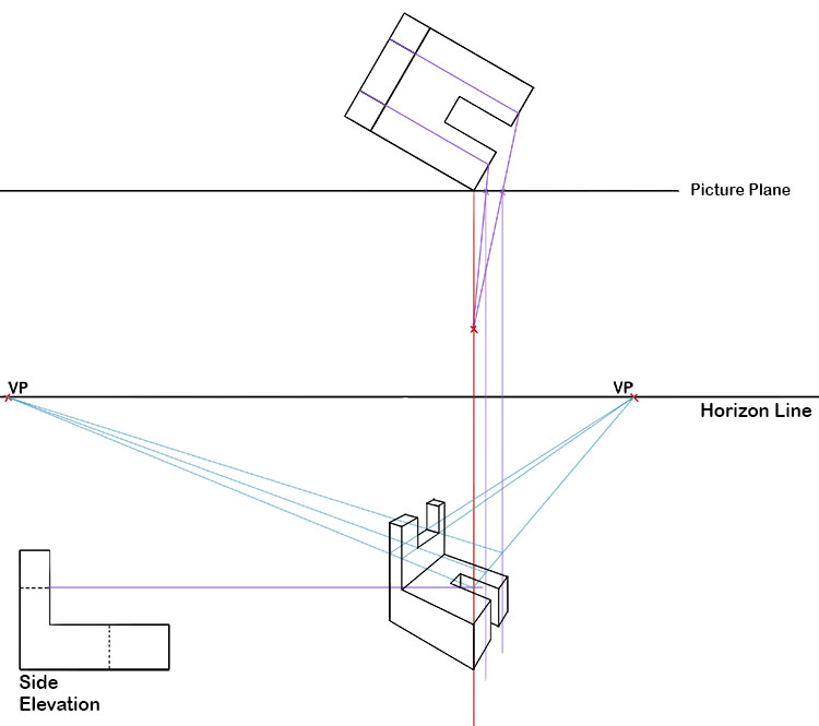
Now you can fill in the remainder of the perspective side elevation.
From here we can connect the corners of what we've drawn so far to our vanishing points which will allow us to draw in the sides.
Next we need to project the corners of the lower cut out section on our object from our plan view to our perspective drawing. Where this line hits the perspective side elevation draw a line that meets the vanishing point on the right.
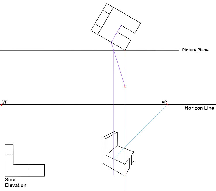
You can now complete the cut out section on the lower part of the object.
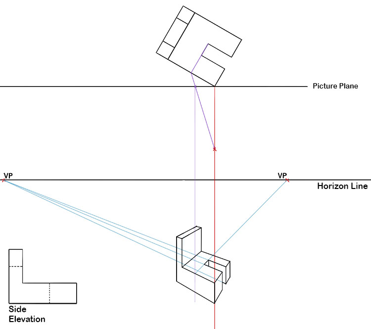
We can repeat the same process to project the cut out of the raised section onto our perspective drawing. We will also need to draw another line from our side elevation and draw lines from where it meets the vertical red line to each vanishing point.
We can now draw more lines out to our vanishing points from where the projection lines meet our vanishing point lines we've just drawn.

We can now fill in the remainder of the cut out.
Finally all of the guide lines can be removed leaving us with an accurate two point perspective drawing.
Technical drawing two point perspective.